





How to read engineering drawings? For many, engineering blueprints can look like a confusing collection of lines, numbers, and symbols. But in reality, a technical drawing is the universal language of manufacturing—a precise set of instructions that connects a designer's vision to a physical product. This beginner's guide is designed to help you start reading technical drawings with confidence. We will break down a typical drawing for sheet metal drawings into four key sections.
Section 1: The Title Block - The Drawing's ID Card
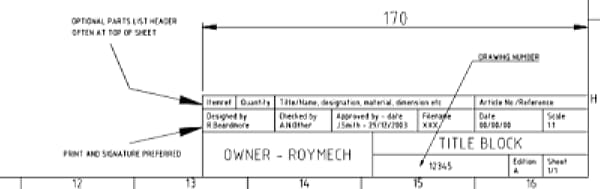
The best place to start is the title block, usually found in the bottom-right corner. Think of it as the drawing's identification card; it contains all the high-level information about the part.
Finding the Part Number and Revision Level
Here you will find the unique Part Number, which is the primary identifier for the component. You'll also see the Revision Level (e.g., Rev A, B, C). It's crucial to always work from the latest revision to avoid costly mistakes.
Understanding Material and Finish Specifications
The title block specifies the required material (e.g., 304 Stainless Steel), its thickness, and any required finish (e.g., Nickel Plating). This information is fundamental to the part's cost and performance.
General Tolerances and Units of Measurement
Look for the general tolerances that apply to all dimensions unless otherwise specified. It will also state the units of measurement used throughout the drawing (e.g., mm or inches).
Section 2: The Views - Seeing the Part from All Angles
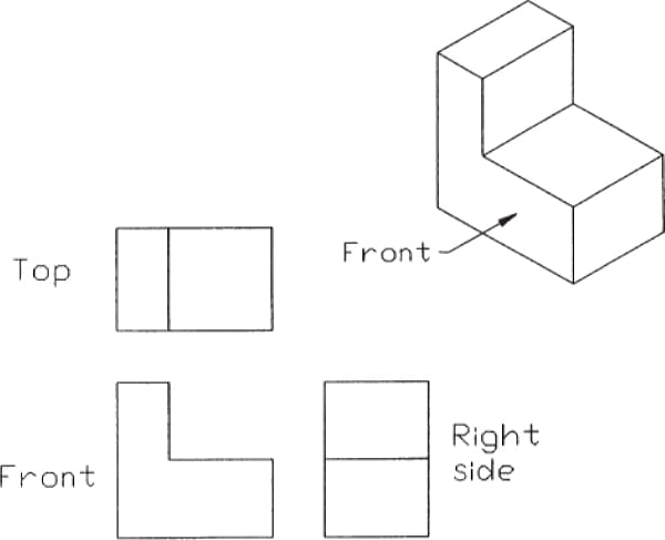
The main body of the drawing shows the part from different viewpoints. This is typically done using orthographic projection.
Understanding Orthographic Projections (Top, Front, Side Views)
This method shows a 3D object in 2D by projecting its views onto different planes. You will typically see a Front View, a Top View, and a Side View. By mentally combining these views, you can build a complete 3D picture of the part in your mind.
Section Views: A Look Inside the Part
A section view is created by an imaginary "cut" through the part to show its internal features. The cut area is marked with crosshatch lines, providing a clear look at the part's internal profile.
Detail Views: Magnifying Critical Features
For small or complex areas, a detail view is used. A circle will highlight a specific area on the main view, which is then shown in a larger scale elsewhere on the drawing to display its features and dimensions more clearly.
Section 3: Dimensions and Tolerances - The Language of Precision
This section contains the precise measurements and allowable variations for every feature. This is the heart of any manufacturing drawing.
How to Read Linear Dimensions
Dimensions are shown using dimension lines with arrows at each end, and a number indicating the measurement. They define the length, width, height, and location of all features.
Understanding Tolerances (e.g., ±0.1mm)
As we covered in our guide to tolerances, a tolerance specifies the acceptable range of variation. A dimension shown as 20.0 ±0.1 mm means the final part must measure between 19.9 mm and 20.1 mm.
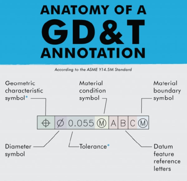
A Brief Introduction to GD&T Symbols (Flatness, Perpendicularity)
You may see special symbols in boxes. This is Geometric Dimensioning and Tolerancing, or GD&T. It's an advanced language for controlling a part's form and orientation. For example, a square symbol with a number indicates how flat a surface must be.
Section 4: Lines and Symbols - Decoding the Drawing
Drawings use a standard set of lines and symbols to convey information efficiently.
Visible, Hidden, and Center Lines
- Visible Lines: Thick, solid lines that show the visible edges of the part.
- Hidden Lines: Dashed lines that show edges or features that are not visible from that view.
- Center Lines: Thin, long-and-short dashed lines that indicate the center of a hole or a symmetrical part.
Understanding Bend Lines and Radii
On sheet metal drawings, you will often see dashed bend lines indicating where the part should be folded. The bend radius is also typically specified, as it is a critical feature for formability and strength.
Common Symbols for Holes (e.g., Countersinks, Counterbores)
Specific symbols are used to define different types of holes. For example, a 'V' shape indicates a countersink (a conical opening for a flat-head screw), while a square shape indicates a counterbore (a flat-bottomed recess for a socket-head screw).
Reading Drawings with Confidence
Learning the language of engineering blueprints is a skill that improves with practice. By understanding these four key sections, you can begin to decode even complex drawings. Remember, when in doubt, the best practice is always to ask. What part of a technical drawing do you find most confusing? The views, the tolerances, or the symbols? Let's help each other out in the comments!
Your Questions on Reading Technical Drawings Answered
What is the difference between a first-angle and a third-angle projection?These are two different standards for arranging the views in an orthographic projection. Third-angle (common in North America) places the top view above the front view. First-angle (common in Europe) places the top view below the front view. The projection method used is usually indicated by a small symbol in the title block.
Why are some dimensions in parentheses?Dimensions in parentheses, for example (20.0), are "reference dimensions." They are provided for informational purposes only and are not used for manufacturing or inspection, as they are controlled by other dimensions on the drawing.
What does "GD&T" stand for and why is it so complex?What does GD&T stand for? It stands for Geometric Dimensioning and Tolerancing. It is a highly precise symbolic language that goes beyond simple size dimensions to control the form, orientation, and location of features relative to each other. Its complexity allows engineers to define a part's functional requirements with much greater detail and clarity.
What is the best way to ask a question about a drawing to a manufacturer?The best way is to be specific. Take a screenshot or picture of the relevant section of the drawing, circle the feature or dimension in question, and send it in an email with a clear, concise question. This visual communication is the most effective way to avoid misunderstandings. For any questions about your drawings, feel free to contact the Pengce Metal team.